
Ελληνική έκδοση (Greek version)
Programmer for PIC24FJ16GA002
This page presents a simple circuit that is connected between the parallel port of a PC and the PIC24FJ16GA002 microcontroller that we want to program. The circuit takes power supply from the system that holds the microcontroller (in the tests the supply voltage was in the range 2.9V to 3.3V). The circuit supports the necessary level conversion for each signal.
The schematic of the circuit follows:
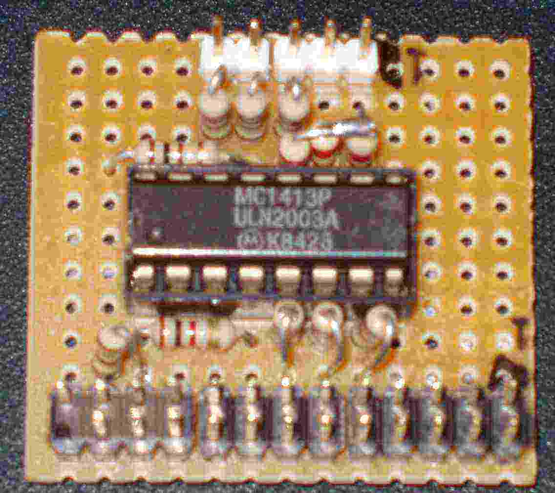
The prototype has been constructed in a general purpose board and is shown in the next photograph:
The PC runs a program that has been developed for this circuit. The two files contain the source code and must be compiled with Visual Basic 2005 Express Edition (freely downloadable from Microsoft's site). I suggest to create a new project and replace the files "form1.vb" and "form1.designer.vb" with the respective files downloaded from this page. The software requires the presence of a driver for the parallel port. This driver is freely available from the page www.logix4u.net/inpout32.htm. A snapshot of the program is shown in the next figure:

The two buttons in the first column control the state of the MCLR signal (run/reset).
The four buttons in the second column must be pressed in order from top to bottom to initiate the communication and to read the ID and the Configuration Words (CW) form the microcontroller. The two last buttons of this column can be used at any time after the initiation of the communication (that is after we press the two first buttons of this column). Attention: after the initiation of the communication, the microcontroller is in programming state. The "MCLR=1" button must be pressed in order to exit this state.
The buttons of the third column are for the actual programming. The first button erases the flash memory (erases the Configuration Words too). The second or the third button reprogram the configuration words. Note: only one of these two buttons must be pressed. The second button is for external oscillator and the third button is for the internal 32KHZ oscillator. For other cases the visual basic code must be modified!!! The forth button of this column reads a .hex file and sends it to the microcontroller. Attention: the microcontroller is still in the programming state. The "MCLR=1" button must be pressed in order to exit this state.
The button of the last column reads the flash memory for verification.
The button "wait100" inserts a 100 seconds delay before any other action. This is done because in my PC some other software meshes with the parallel port and this is a (not good) way to overcome this problem.
The button "Verify communication with MCU" performs all the tasks of the second column and then exits the programming state (MCLR=1).
The button "Program MCU" performs all the tasks of the second and third column (with CW=3F7F-FACC) and then exits the programming state (MCLR=1).
In the next version of the software a simpler method for setting the configuration words will be implemented.