VCO
VCO is built around a 32-bits phase ramp that goes from zero (0) (which is the initial value) to its maximum value FFFFFFFF(hex). In each tick (48 KHz interrupt, LRCK) the ramp is incremented by a value “step” (32-bits, unsigned). Any overflow is ignored, so the value after FFFFFFFF hex is 00000000. The period of the ramp corresponds to the period of the produced frequency. The 32-bits are necessary to give accurate T-values in a broad range from 15 HZ to 20KHz. 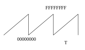
The step value determines the period T of the ramp (and equivalently the frequency (f) as T = 1/f). The step is calculated as: 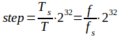 , where fs is the sampling frequency (=48KHZ), Ts is the respective period and f is the desired frequency. Note that always Ts < T/2, or fs > 2f).
Example values:
f=440HZ gives step = 0258BF26(hex) = 39370534(dec),
f = 15Hz gives step = 00147AE1(hex) =1342177(dec).
, where fs is the sampling frequency (=48KHZ), Ts is the respective period and f is the desired frequency. Note that always Ts < T/2, or fs > 2f).
Example values:
f=440HZ gives step = 0258BF26(hex) = 39370534(dec),
f = 15Hz gives step = 00147AE1(hex) =1342177(dec).
Voltage-to-Step converter
The frequency is controlled by voltage in a 1V/octave schema. The minimum value of the input voltage is 0 volts that corresponds to a base frequency set to 15 Hz. Any increase of the input of 1 Volt doubles the output frequency, so 1V gives 30 HZ, 2 V give 60 Hz, 3V give 120 Hz and so on. The equation that describes this is:
f=15∙2V where V is the input voltage.
The “voltage” number is in s4.11 format (signed, 4 bits integer part and 11 bits decimal part). We can separate the integer and decimal part, and we have:
f=15∙2V = 15∙2(int part+decimal part) = 15∙2int part∙2dec part.
The output f is then converted to step value for the ramp: 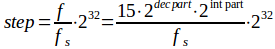 .
A Look-up Table (LUT) maps the
.
A Look-up Table (LUT) maps the 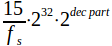 part (which is equivalent to input “voltage” that lies in the range 0 to 1V) to the desired step value. The LUT has 211 values (as the decimal part of the “voltage” has 11 bits). These values are calculated off-line and are stored in the MCU’s EPROM as 32-bit numbers. The value that comes out from this LUT must be shifted to the left by “int part” bits, which implements the multiplication by 2int part.
The maximum frequency is 20KHz, so the maximum value of the int part is 10. In order to keep the maximum accuracy of the step values, the LUT is stored already shifted to the left 10 bits, so the value that comes out from the LUT must be right-shifted “10 - (int part)” bits.
part (which is equivalent to input “voltage” that lies in the range 0 to 1V) to the desired step value. The LUT has 211 values (as the decimal part of the “voltage” has 11 bits). These values are calculated off-line and are stored in the MCU’s EPROM as 32-bit numbers. The value that comes out from this LUT must be shifted to the left by “int part” bits, which implements the multiplication by 2int part.
The maximum frequency is 20KHz, so the maximum value of the int part is 10. In order to keep the maximum accuracy of the step values, the LUT is stored already shifted to the left 10 bits, so the value that comes out from the LUT must be right-shifted “10 - (int part)” bits.
The input to the Voltage-to-Step converter comes from CV and FM and the controls “coarse” and “fine”. The controls are implemented as parameter values.
“coarse” is implemented by linearly mapping the parameter value (0 to 240) to the range -10.0 to 10.0 in steps of 1/12, corresponding to semitones from -10 octaves to +10 octaves.
“fine” is implemented by values from -128 to 127 that represent “Voltages” from -0.0625 to 0.062012 corresponding to -0.75 to 0.75 of semitones
Both parameters are summed with the input CV. Input value FM is passed through a multiplication factor (factor_FM). This factor is implemented by a log mapping of the parameter value (0 to 200) to the range 0.0 to 1.0 in .16 format. (change it: 0.0 to 2.0)
wave shaping
Sawtooth: The MSBit is complemented. This converts the unsigned number to signed, balanced at zero. This number is then divided by 2 to make 1-bit room for possible overshoot due to the BLEP method that will be applied. The resulting number can be considered to be in -1.0 to 1.0 range in s1.14 format (signed, one integer bit, 14 decimal bits).
BLEP:
If we use this “trivial” sawtooth signal to drive the DAC, we will face the “alias” problem. The alias problem occurs whenever there is a step transition in the signal. The harmonics implied with this step transition exceed the Nyquist frequency and are “reflected” back to the audible spectrum. The solution is to produce a “step” that has no harmonics above the Nyquist frequency. So, instead of a step like the one in fig.1, we must produce a step like that in fig.2 (that is the step of fig.1 passed through a low-pass filter that cuts all the frequencies above the Nyquist limit)
figure 1: step transition figure 2: band-limited step transition
BLEP method says that we must subtract these two signals (fig.2 – fig.1) and produce the signal shown in fig.3
figure 3: the difference
Now, the signal of fig.2 can be produced by adding (fig1 + fig.3).
For a step-down transition, just take the opposite difference (or equivalently, subtract instead of add).
Production of the correction signal (3 points per side, 2048 samples per point):
1) Generate numbers from a sinc (=sin(x)/x) function: , y=0 for i=0.
The graphical representation of y is shown in fig.4
2K = 2048 samples
figure 4: sinc function
Only the 6K left samples are calculated, as the 6K right samples are identical to the left. Note that the actual range of the samples is from -3π to 3π.
2) Multiply the sinc function with a window function (Blackman, Hann, etc.)
Blackman: , N-1 = 12K, 0<= n <= 6K (for left 6K half)
Hann: , c<= n <= 6K (for left 6K half)
figure 5: window function
3) Integrate (sum up) the left 6K values
figure 6: the result of the integration. “sumx” is the final point of the left half (6K values)
4) Normalize the values by dividing with “sumx”
figure 7: normalized values
The resulting floating-point numbers are then multiplied with the integer value 16384 (= 214). This gives numbers with maximum 1.0 in s1.14 format (signed, one integer bit, 14 decimal bits).
BLEP is implemented with 3+3 points.
Square: Compare the ramp value with the PWM level. If the ramp is less that the PWM level, then set the output voltage as min, if it is greater, then set the output voltage as max. The PWM level is calculated as the sum of the PW parameter and the PWM input attenuated (linearily) by the PWM parameter. BLEP is also used.
Sine: A LUT of 1024 points is used. The 10 MSBits of the ramp are used as index to a LUT and the next 6 LSBits are used in a linear interpolation. Next figure shows the interpolation operation. The algorithm follows:
, where (# of LSBits) = 6
find y (LUT)
find next y (LUT)
calc (next y – y) (signed)
calc [(dec part of X) * (next y – y)] (signed)
shift right (divide) (signed)
add to y (signed)
The resulting value is in the range 00000000 to FFFFFFFF. The output is then calculated as in the saw-tooth wave (without the BLEP of course).
Triangle: a bit test is performed on the MSBit of the ramp-voltage. 0: output = ramp voltage X 2. 1: output = (max value – ramp value) X 2. The multiplication is performed with a left shift one bit. The resulting value is in the range 00000000 to FFFFFFFF. The output is calculated as in the saw-tooth wave.
NOTES
Log-mapping:
The parameter value from the control section is linear, so a linear-to-logarithmic conversion is used. The characteristic of this function is y=(x/200)^2.8. (other functions can also be used, e.g. y=(x/200)^3.14 or y= (exp(x/37.71233) – 1)/200). The resulting function must produce y=0.5 for x = 0.8 and y=0.14 for x=0.5 to resemble the behavior of “real” log potentiometers. The following diagram shows the plot of the used function.
Calculation of the LUT for the Voltage-to-Step converter.
Dim i As Integer
Dim Trate As Double
Dim Step_var As UInt64
Dim s As String
For i = 0 To 2048
Trate = (2 ^ (i / 2048))
Step_var = Trate * (15 / 48000) * (2 ^ 32)
s = Hex(Step_var)
Next i
Calculation of the LUT for the “coarse” control.
int i;
double X;
int IX[120];
for (i = 0; i<120; i++) // the positive values
{
X = (i + 1.0) / 12.0;
IX[i] =(int) (X * pow(2,11));
}
Calculation of the LUT for the log parameter (FMin, Out)
Dim i As Integer
Dim X As Double
Dim IX As UInt64
Dim s As String
For i = 0 To 200
X = Math.Pow(i / 200.0, 2.8)
IX = X * (2 ^ 15) '1.15 unsigned !!
IX = (IX) And (&HFFFF)
s = Hex(IX)
Next i
Calculation of the LUT for the sin
Dim i As Integer
Dim X As Double
Dim IX As UInt64
Dim s As String
For i = 0 To 1024
X = Math.Sin((i / 1024) * (2 * 3.1415926535897931))
If X >= 0 Then
IX = X * ((2 ^ 15) - 1)
IX = (IX) And (&HFFFF)
Else
X = -X
IX = X * ((2 ^ 15) - 1)
IX = (IX) And (&HFFFF)
IX = IX Xor &HFFFF
IX = IX And &HFFFF
IX = IX + 1
IX = IX And &HFFFF
End If
s = Hex(IX)
Next I
Calculation of BLEP residual
#include