Use this block to repeat sequences of code. Set the condition that will end
the loop: elapsed time, the number of repetitions, a logic signal or a
sensor. You can also set a loop to go on forever.
Display settings
Adding blocks to the Loop block
Moving the Loop block
Configuring the Loop block
Display settings
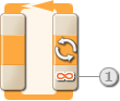
- When a Loop block’s action property is set to “Forever,” an infinity
symbol (∞) is displayed at the bottom of the trailing portion of the
block.
- If the “Show Counter” checkbox is selected in the configuration
panel, a plug will appear that will allow you to use the number of
completed loops as an input elsewhere in your program (if you connect a
data wire from the plug to another block’s data hub). You can also use
current count to control the loop itself. (See the Count setting in the
Configuring the Loop Block section below).
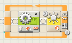
- If you choose for a sensor to control the loop, the trailing portion
of the Loop block will expand in size revealing an icon for the chosen
sensor. For example, if you choose a Light Sensor to control the loop, a
Light Sensor icon will be displayed in the expanded portion of the
block. Also, any relevant information about the chosen control property
will displayed at the bottom of the block.
Adding blocks to the Loop block
If a Loop block is placed on the sequence beam, a short section of the
beam will appear inside the Loop block; programming blocks dragged on top of
this portion of the sequence beam will snap to it. Any new blocks dragged
inside a loop that already contains programming blocks will cause the frame
to expand sideways. This will make room for the new blocks to snap to the
sequence beam.
Moving the Loop block
The Loop block can only be selected and moved by clicking on the block
itself; clicking on the surrounding frame or on the blocks inside the frame
will not work.
Configuring the Loop Block
The Control property pull-down menu will let you choose from five primary
conditions that will affect your loop:
Forever
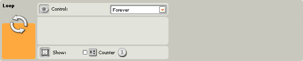
If you choose “Forever,” any programming blocks within the loop will
repeat forever without interruption.
- Check the “Show Counter” checkbox to use the number of loops
completed as input to another block. (Example: to increase a Motor
block’s Power.)
Time
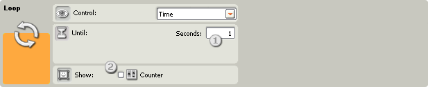
If you choose “Time,” the programming blocks within the loop will repeat
until a certain number of seconds have passed. After the time period is up,
the loop will end.
- Use this box to type in the number of seconds that the loop should
run. If you choose 5 seconds, for example, the loop will end after 5
seconds have passed.
- If the “Show Counter” checkbox is selected in the configuration
panel, a plug will appear that will allow you to use the number of
completed loops as an input elsewhere in your program (if you connect a
data wire from the plug to another block’s data hub).
Touch Sensor
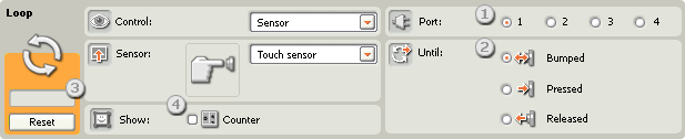
If you choose “Touch Sensor,” the programming blocks within the loop will
repeat until a touch sensor is bumped, pressed, or released. Then the loop
will end and the program will go on.
- Choose the port that the touch sensor is connected to.
- Use the radio buttons to specify whether you want the touch sensor
to be bumped, pressed, or released to end the loop. Choose Bumped if you
want the block to be triggered after a quick press and release of the
touch sensor (less than 0.5 seconds in duration). Choose Pressed if you
want the block to be triggered at the instant the touch sensor is
pressed in. Choose Released if you want the block to be triggered at the
instant the touch sensor is released.
- The feedback box will let you test your touch sensor. When the
sensor is activated on your robot, the number “1” will be displayed
here. Use the reset button to clear the feedback box.
- If the “Show Counter” checkbox is selected in the configuration
panel, a plug will appear that will allow you to use the number of
completed loops as an input elsewhere in your program (if you connect a
data wire from the plug to another block’s data hub).
Sound Sensor
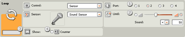
If you choose “Sound Sensor,” the programming blocks within the loop will
repeat until the sound sensor detects sound in a certain range.
- Choose the port where your sound sensor is plugged in. By default,
the block will be set to port 2 for a sound sensor.
- Use the slider to set the trigger value or type a value directly
into the input box. Select the radio button to the right of the slider
if you want the loop to end when sound levels are higher than the
trigger value; select the left radio button to end the loop when sound
levels are lower than the trigger value. You can also use the pull-down
menu to set the portion of the slider that will end the loop.
- The feedback box displays the current sound reading (0-100%). You
can use it to try out different trigger values.
- If the “Show Counter” checkbox is selected in the configuration
panel, a plug will appear that will allow you to use the number of
completed loops as an input elsewhere in your program (if you connect a
data wire from the plug to another block’s data hub).
Light Sensor
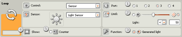
If you choose “Light Sensor,” the programming blocks within the loop will
repeat until a light sensor measures a certain intensity of light. Then the
loop will end and the program will advance.
- Choose the port where your light sensor is plugged in. By default,
the block will be set to port 3 for a light sensor.
- Use the slider to set the trigger value or type a value directly
into the input box. Select the radio button to the right of the slider
if you want the loop to end when light levels are higher than the
trigger value; select the left radio button to end the loop when light
levels are lower than the trigger value. You can also use the pull-down
menu to set the portion of the slider that will end the loop.
- If you check the “Generated Light” checkbox, the light sensor will
turn on its own small light source and detect this light if it is
reflected back to it.
- The feedback box will display the current light reading.
- If the “Show Counter” checkbox is selected in the configuration
panel, a plug will appear that will allow you to use the number of
completed loops as an input elsewhere in your program (if you connect a
data wire from the plug to another block’s data hub).
Ultrasonic Sensor
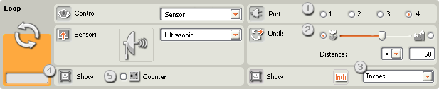
If you choose “Ultrasonic Sensor,” the programming blocks within the loop
will repeat until the ultrasonic sensor detects an object at a certain
distance.
- Choose the port where your ultrasonic sensor is plugged in. By
default, the block will be set to port 4 for an ultrasonic sensor.
- Use the slider to set the trigger value or type a value directly
into the input box. Select the radio button to the left of the slider if
you want the loop to end when the ultrasonic sensor detects an object
closer than the trigger value; select the right radio button to end the
loop when the ultrasonic sensor detects an object farther away than the
trigger value. You can also use the pull-down menu to set the portion of
the slider that will end the loop.
- Select to read values in Centimeters or Inches.
- The feedback box will display the current ultrasonic sensor reading.
- If the “Show Counter” checkbox is selected in the configuration
panel, a plug will appear that will allow you to use the number of
completed loops as an input elsewhere in your program (if you connect a
data wire from the plug to another block’s data hub).
NXT Buttons
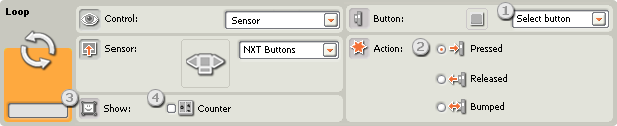
If you choose “NXT Buttons,” the programming blocks within the loop will
repeat until the chosen NXT buttons is bumped, pressed, or released.
- Select which NXT button will send out a “true” signal when activated
(and end the loop).
- Choose Bumped if you want the chosen button to be activated after a
quick press and release. Choose Pressed if you want the chosen button to
be activated at the instant the button is pressed in. Choose Released if
you want the chosen button to be activated at the instant the button is
released.
- The feedback box will display a “1” when the chosen NXT button is
bumped, pressed or released (according to the configuration you’ve set).
- If the “Show Counter” checkbox is selected in the configuration
panel, a plug will appear that will allow you to use the number of
completed loops as an input elsewhere in your program (if you connect a
data wire from the plug to another block’s data hub).
(Built-in) Rotation Sensor
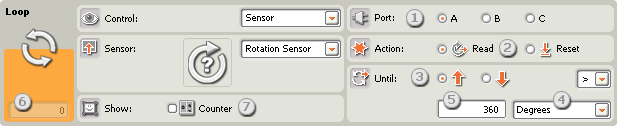
If you choose to “read” a rotation sensor, the programming blocks within
the loop will repeat until the rotation sensor reaches a certain value; then
the loop will end and the program will advance. If you choose to “reset” the
rotation sensor, the sensor will be reset to zero after each loop; the block
will continue to loop until the rotation sensor can reach the trigger value
during one of the loops.
- Choose the port where your motor is plugged in.
- Choose to read or reset a rotation sensor.
- Use the radio buttons to set the direction you want: forwards or
backwards.
- Choose to count either Rotations or Degrees by using the pull-down
menu.
- Type the number of rotations or degrees you want to go by before the
loop is ended (allowing your program to go forward).
- The feedback box will display the current number of rotations or
degrees. Use the reset button to clear the feedback box.
- If the “Show Counter” checkbox is selected in the configuration
panel, a plug will appear that will allow you to use the number of
completed loops as an input elsewhere in your program (if you connect a
data wire from the plug to another block’s data hub).
Timer
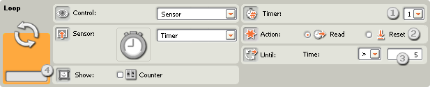
If you choose to “read” a timer, the programming blocks within the loop
will repeat until one of the NXT’s internal timers reaches a certain time
value; then the loop will end and the program will advance. If you choose to
“reset” a timer, the timer will be reset after each loop; the block will
continue to loop until the timer can reach its trigger value during one of
the loops.
- Choose the NXT timer that you would like to monitor.
- Choose to read or reset a timer.
- Type a time value (in seconds) in the input box.
- If the “Show Counter” checkbox is selected in the configuration
panel, a plug will appear that will allow you to use the number of
completed loops as an input elsewhere in your program (if you connect a
data wire from the plug to another block’s data hub).
Receive Message
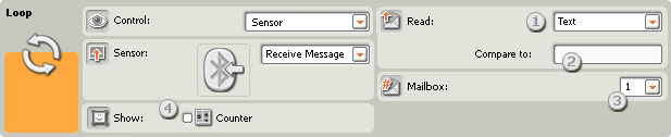
If you choose “Receive Message,” the programming blocks within the loop
will repeat until your NXT receives a certain Bluetooth message. Then the
loop will end and the program will advance.
- The pull-down menu will let you select the message type (Text,
Number, or Logic) of the message that you expect to receive.
- To compare the incoming message to a test message, either type in
the test text or number (if you have chosen Text or Number respectively
as the format), or use the radio buttons to choose the test logic value
(true or false).
- Choose the mailbox number where the incoming message will arrive.
- If the “Show Counter” checkbox is selected in the configuration
panel, a plug will appear that will allow you to use the number of
completed loops as an input elsewhere in your program (if you connect a
data wire from the plug to another block’s data hub).
Touch* Sensor
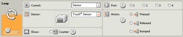
If you choose “Touch* Sensor,” the programming blocks within the loop
will repeat until a touch* sensor is bumped, pressed, or released. Then the
loop will end and the program will go on.
- Choose the port that the touch* sensor is connected to. By default,
the block will be set to port 1 for a touch sensor.
- Use the radio buttons to specify whether you want the touch sensor
to be bumped, pressed, or released to end the loop. Choose Bumped if you
want the block to be triggered after a quick press and release of the
touch sensor (less than 0.5 seconds in duration). Choose Pressed if you
want the block to be triggered at the instant the touch sensor is
pressed in. Choose Released if you want the block to be triggered at the
instant the touch sensor is released.
- The feedback box will let you test your touch sensor. When the
sensor is activated on your robot, the number “1” will be displayed
here. Use the reset button to clear the feedback box.
- If the “Show Counter” checkbox is selected in the configuration
panel, a plug will appear that will allow you to use the number of
completed loops as an input elsewhere in your program (if you connect a
data wire from the plug to another block’s data hub).
Light* Sensor
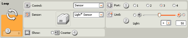
If you choose “Light* Sensor,” the programming blocks within the loop
will repeat until a light* sensor measures a certain intensity of light.
Then the loop will end and the program will advance.
- Choose the port where your light* sensor is plugged in. By default,
the block will be set to port 3 for a light sensor.
- Use the slider to set the trigger value or type a value directly
into the input box. Select the radio button to the right of the slider
if you want the loop to end when light levels are higher than the
trigger value; select the left radio button to end the loop when light
levels are lower than the trigger value. You can also use the pull-down
menu to set the portion of the slider that will end the loop.
- The feedback box will display the current light reading.
- If the “Show Counter” checkbox is selected in the configuration
panel, a plug will appear that will allow you to use the number of
completed loops as an input elsewhere in your program (if you connect a
data wire from the plug to another block’s data hub).
Rotation* Sensor
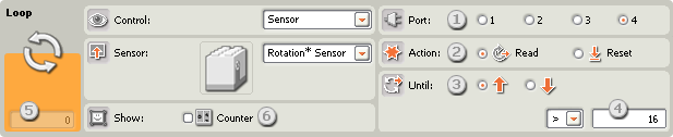
If you choose to “read” a rotation* sensor, the programming blocks within
the loop will repeat until the rotation sensor reaches a set number of ticks
(16 to a rotation); then the loop will end and the program will advance. If
you choose to “reset” the rotation* sensor, the sensor will be reset to zero
after each loop; the block will continue to loop until the rotation* sensor
can reach the trigger value during one of the loops.
- Choose the port where your motor is plugged in.
- Choose to read or reset a rotation* sensor.
- Use the radio buttons to set the direction you want: forwards or
backwards.
- Type the number of ticks (16 to a rotation) you want to go by before
the loop is ended (allowing your program to go forward).
- The feedback box will display the current number of ticks (16 to a
rotation). Use the reset button to clear the feedback box.
- If the “Show Counter” checkbox is selected in the configuration
panel, a plug will appear that will allow you to use the number of
completed loops as an input elsewhere in your program (if you connect a
data wire from the plug to another block’s data hub).
Temperature* Sensor
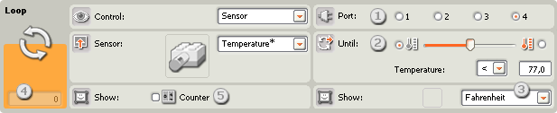
If you choose “Temperature* Sensor,” the programming blocks within the
loop will repeat until a temperature* sensor measures a certain temperature.
Then the loop will end and the program will advance.
- Choose the port where the temperature sensor is plugged in. By
default, the block will be set to port 4 for a temperature sensor.
- Use the slider to set the trigger value or type a value directly
into the input box. Select the radio button to the right of the slider
if you want the block to be triggered by temperatures higher than the
trigger value; select the left radio button to trigger the block with
temperatures lower than the trigger value. You can also use the
pull-down menu to set the “true” portion of the slider.
- Select to read values in Celsius or Fahrenheit.
- The feedback box displays the current temperature reading.
- If the “Show Counter” checkbox is selected in the configuration
panel, a plug will appear that will allow you to use the number of
completed loops as an input elsewhere in your program (if you connect a
data wire from the plug to another block’s data hub).
Count
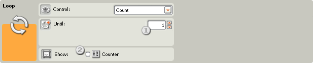
If you choose “Count,” any programming blocks within the loop will repeat
until the Counter reaches a set number of repetitions.
- Use this box to type in the number of repetitions that will end the
loop. If you type “2,” for example, the loop will end after the
programming blocks in the loop have been run twice.
- Check the “Show Counter” checkbox so that you can wire the left side
of the loop to the right side (where the “count” plug appeared). With
the left and right sides connected, the program will be able to count
the number of completed loops and leave the loop when the count reaches
the number you set.
Logic
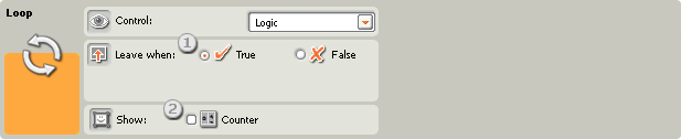
If you choose “Logic” and connect an input data wire to the Loop block’s
trailing portion, any programming blocks within the loop will repeat as long
as the Loop block is receiving a true or false logic signal through the data
wire. When a specified logic signal is received, the loop will end.
- Choose which type of logic signal, true or false, will end the loop.
- If the “Show Counter” checkbox is selected in the configuration
panel, a plug will appear that will allow you to use the number of
completed loops as an input elsewhere in your program (if you connect a
data wire from the plug to another block’s data hub).
