Use this block to choose between two sequences of code. For example, when
configured with a touch sensor, the switch block might run one series of
blocks when the sensor is pressed and another when the touch sensor is not.
Display settings
Adding blocks to the Switch block
Moving the Switch block
Configuring the Switch block
Display settings:

- This icon indicates the sensor or other condition that will cause
the block to choose between the two rows of programming blocks. In this
case the current status of a touch sensor will cause the program to
switch.
- The upper blocks will run if the touch sensor is pressed.
- The lower block will run if the touch sensor is not being pressed.

- If you’ve chosen to control the Switch block using the Value
condition, a data wire plug will appear at the bottom of the leading
edge of the Switch block; you will have to attach a logic or number data
wire to this plug from some other block to control the switch.

- By de-selecting the “Display Flat View” checkbox, the Switch block
will use a tabbed interface to show the alternative sequences of
programming blocks. By clicking on a tab, you will be able to view and
edit the blocks and see which condition will cause those particular
blocks to run.

Note:
When you want to attach a data wire from outside to a block inside the
Switch block, you need to de-select the “Display Flat View” so the
Switch block appears with its tabbed interface.
Adding blocks to the Switch block:
Add blocks by dragging them over the empty spaces within the Switch
block’s surrounding frame. The Switch block’s interior will expand so the
block can fit and snap into place. If there are already blocks within the
frame, drag any additional blocks over the desired connection point on the
sequence beam and the adjacent blocks will shift sideways allowing the new
blocks to snap into place.
Moving the Switch block:
The Switch block can only be selected and moved by clicking on the block
itself; clicking on the surrounding frame or on the blocks inside the frame
will not work.
Configuring the Switch block:
The Control property pull-down menu will let you choose from two primary
conditions that will affect your loop:
-
Value
- Sensor (which will activate a second pull-down menu)
Value
A Switch block set to “Value” can accept either logic or number input
through a data wire connected to its leading edge. It will detect the kind
of data wire attached to its plug (i.e., logic or number) and offer
different switching options for each.
If you connect a logic (true/false) data wire, the program will run the
programming blocks on the upper sequence beam when the Switch block is
receiving a “true” signal. If the block is receiving a “false” signal, the
program will run the blocks on the lower sequence beam.
If you connect a number or a text data wire, you can specify the exact
input that will cause the programming blocks on the different sequence beams
to run. Furthermore, if the Display Flat View option is de-selected, you can
switch to more than two sets of programming blocks.

- This field will show the type of input detected by the block.
- By de-selecting the “Display Flat View” checkbox, the Switch block
will use a tabbed interface to show the alternative sequences of
programming blocks. By clicking on a tab, you’ll be able to view and
edit the blocks and see what condition will cause those particular
blocks to run.
- Each row in the table represents a switching option. When “Display
Flat View” is checked, the upper most option, number 1, represents the
condition that will cause the programming blocks on the upper sequence
beam to run. The second option, number 2, represents the condition that
will cause the blocks on the lower sequence beam to run.
If a Number
or Text data wire is connected to the Switch block and the “Display Flat
View” is de-selected (enabling the tabbed interface), you can add
additional rows to the table that will control more sequences of blocks
as in the image below.

- This box serves two roles. When the Switch block is set for logic
input, this box’s pull-down arrow will let you flop the blocks on the
two sequence beams, changing which one group will be activated by a
“true” signal. When the Switch block is set for number input, use this
box to type in the number that will activate a certain switching option.
- These buttons will let you add and delete switching options. They
are only active when the Flat View is de-selected and a number or text
data wire is connected to the Switch block’s input plug.
- The “*” button will set the default option in the list. When the
Switch block is set for number data and a signal arrives that does not
match one of the set numerical options, the block will run whichever
option is set as the default.
Touch Sensor
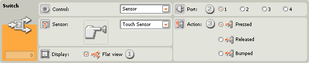
Choose this control property if you want the condition of a touch sensor
to determine which way your program will switch.
- By de-selecting the “Display Flat View” checkbox, the Switch block
will use a tabbed interface to show the alternative sequences of
programming blocks. By clicking on a tab, you will be able to view and
edit the blocks and see which condition will cause those particular
blocks to run.
- Choose the port where your touch sensor is plugged in. By default,
the block will be set to port 1 for a touch sensor. You can change this
selection if you need to.
- With the radio buttons you can specify which touch sensor condition
(Pressed, Released, or Bumped) will cause the Switch block to run the
blocks in the upper switch area; the lower switch area will run when no
action occurs. If you choose Pressed, the block will switch at the
instant the touch sensor is pressed in. If you choose Released, the
block will switch at the instant the touch sensor is released. If you
choose Bumped, the block will switch at the instant the touch sensor is
bumped.
Sound Sensor

Choose this control property if you want the readings from a sound sensor
to determine which way your program will switch.
- By de-selecting the “Display Flat View” checkbox, the Switch block
will use a tabbed interface to show the alternative sequences of
programming blocks. By clicking on a tab, you will be able to view and
edit the blocks and see which condition will cause those particular
blocks to run.
- Choose the port where your sound sensor is plugged in. By default,
the block will be set to port 2 for a sound sensor. You can change this
selection if you need to.
- Use the slider to set the trigger value or type a value directly
into the input box. At the default setting of 50%, the program will run
the programming blocks on the upper sequence beam if the sound sensor
detects sound levels above 50% and run the blocks on the lower sequence
beam if the sound level is less than 50%.
Light Sensor

Choose this control property if you want the readings from a light sensor
to determine which way your program will switch.
- By de-selecting the “Display Flat View” checkbox, the Switch block
will use a tabbed interface to show the alternative sequences of
programming blocks. By clicking on a tab, you will be able to view and
edit the blocks and see which condition will cause those particular
blocks to run.
- Choose the port where your light sensor is plugged in. By default,
the block will be set to port 3 for a light sensor. You can change this
selection if you need to.
- Use the slider to set the trigger value or type a value directly
into the input box. At the default setting of 50%, the program will run
the programming blocks on the upper sequence beam if the light sensor
detects light levels above 50% and run the blocks on the lower sequence
beam if the light level is less than 50%.
- If you check the “Generated Light” checkbox, the light sensor will
turn on its own small light source and detect this light if it is
reflected back to it.
- The feedback box displays the current light reading (0-100%).
Ultrasonic Sensor

Choose this control property if you want the distance readings from an
ultrasonic sensor to determine which way your program will switch.
- By de-selecting the “Display Flat View” checkbox, the Switch block
will use a tabbed interface to show the alternative sequences of
programming blocks. By clicking on a tab, you will be able to view and
edit the blocks and see which condition will cause those particular
blocks to run.
- Choose the port where your ultrasonic sensor is plugged in. By
default, the block will be set to port 4 for an ultrasonic sensor. You
can change this selection if you need to.
- Use the slider to set the trigger value or type a value directly
into the input box. At the default setting of 50 (127), the program will
run the programming blocks on the upper sequence beam if the ultrasonic
sensor detects an object at farther than 50 inches (127 cm) and run the
blocks on the lower sequence beam if it detects an object at less than
50 inches (127 cm).
- Select to read values in Centimeters or Inches.
- The feedback box displays the current ultrasonic reading.
NXT Buttons

If you choose “NXT Buttons,” the program will run the programming blocks
on the upper sequence beam when the chosen NXT button is bumped, pressed, or
released. It will run the blocks on the lower sequence beam when no action
occurs.
- Select which NXT button will send out a “true” signal when activated
(and end the loop).
- Choose Bumped if you want the button to be activated after a quick
press and release. Choose Pressed if you want the button to be activated
at the instant the button is pressed in. Choose Released if you want the
button to be activated at the instant the button is released.
Built-in Rotation Sensor

Choose this control property if you want the number of counted rotations
or degrees to determine which way your program will switch.
- By de-selecting the “Display Flat View” checkbox, the Switch block
will use a tabbed interface to show the alternative sequences of
programming blocks. By clicking on a tab, you will be able to view and
edit the blocks and see which condition will cause those particular
blocks to run.
- If you choose "Reset," the Switch block will read the rotation
sensor's value and then reset the sensor's value to zero. If you choose
"Read," the sensor's value will not be reset.
- Choose the port you would like to monitor.
- Use the radio buttons to set the direction you want: forwards or
backwards.
- Choose to count either Rotations or Degrees by using the pull-down
menu.
- Type a value into the input box to set the trigger point. The
default value is 360 degrees. At this setting, the program will run the
programming blocks on the upper sequence beam if the number of counted
degrees is more than 360 and run the blocks on the lower sequence beam
if the number of degrees is less than 360.
- The feedback box will display the current number of rotations or
degrees.
Timer

Choose this control property if you want a timer’s current value to
determine which way your program will switch.
- By de-selecting the “Display Flat View” checkbox, the Switch block
will use a tabbed interface to show the alternative sequences of
programming blocks. By clicking on a tab, you will be able to view and
edit the blocks and see which condition will cause those particular
blocks to run.
- If you choose "Reset," the Switch block will read a timer's value
and then reset the timer to zero. If you choose "Read," the timer will
not be reset.
- Choose which of the NXT’s three timers you would like to monitor.
- Type a value into the input box to set the trigger point. The
default value is 5 seconds. At this setting, the program will run the
programming blocks on the upper sequence beam if the current time is
more than 5 seconds and run the blocks on the lower sequence beam if the
current time is less than 5 seconds.
Receive Message

If you choose “Receive Message,” the program will run the programming
blocks on the upper sequence beam when a certain Bluetooth message is
received. It will run the blocks on the lower sequence beam if the message
is not received.
- The pull-down menu will let you select the message type (Text,
Number, or Logic) of the message that you expect to receive.
- To compare the incoming message to a test message, either type in
the test text or number (if you have chosen Text or Number respectively
as the format), or use the radio buttons to choose the test logic value
(true or false). If any incoming message matches the test message or
value, the program will run the blocks on the upper sequence beam.
Otherwise, the blocks on the lower sequence beam will run.
- Choose the message number where the incoming message will arrive.
Touch* Sensor

Choose this control property if you want the condition of a touch* sensor
to determine which way your program will switch.
- By de-selecting the “Display Flat View” checkbox, the Switch block
will use a tabbed interface to show the alternative sequences of
programming blocks. By clicking on a tab, you’ll be able to view and
edit the blocks and see what condition will cause those particular
blocks to run.
- Choose the port where your touch sensor is plugged in. By default,
the block will be set to port 1 for a touch sensor.
- With the radio buttons you can specify which touch sensor condition
(Pressed, Released, or Bumped) will cause the Switch block to run the
blocks in the upper switch area; the lower switch area will run when no
action occurs. If you choose Pressed, the block will switch at the
instant the touch sensor is pressed in. If you choose Released, the
block will switch at the instant the touch sensor is released. If you
choose Bumped, the block will switch at the instant the touch sensor is
bumped.
Light* Sensor

Choose this control property if you want the readings from a light*
sensor to determine which way your program will switch.
- By de-selecting the “Display Flat View” checkbox, the Switch block
will use a tabbed interface to show the alternative sequences of
programming blocks. By clicking on a tab, you’ll be able to view and
edit the blocks and see what condition will cause those particular
blocks to run.
- Choose the port where your light sensor is plugged in. By default,
the block will be set to port 3 for a light sensor. You can change this
selection if you need to.
- Use the slider to set the trigger value or type a value directly
into the input box. At the default setting of 50%, the program will run
the programming blocks on the upper sequence beam if the light sensor
detects light levels above 50% and run the blocks on the lower sequence
beam if the light level is less than 50%.
- The feedback box displays the current light reading (0-100%).
Rotation* Sensor

Choose this control property if you want the number of counted ticks (16
to a rotation) to determine which way your program will switch.
- By de-selecting the “Display Flat View” checkbox, the Switch block
will use a tabbed interface to show the alternative sequences of
programming blocks. By clicking on a tab, you’ll be able to view and
edit the blocks and see what condition will cause those particular
blocks to run.
- Choose the port you would like to monitor.
- Use the radio buttons to set the direction you want: forwards or
backwards.
- Type a value into the input box to set the trigger point. The
default value is 16 ticks (16 to a rotation). With the pull-down menu
set to “>”, the program will run the programming blocks on the upper
sequence beam if the number of counted ticks is more than 16 and run the
blocks on the lower sequence beam if the number of ticks is less than
16. Setting the pull-down menu to “<” will reverse the above scenario.
- The feedback box will display the current number of ticks.
Temperature* Sensor

Choose this control property if you want the temperature to determine
which way your program will switch.
- By de-selecting the “Display Flat View” checkbox, the Switch block
will use a tabbed interface to show the alternative sequences of
programming blocks. By clicking on a tab, you’ll be able to view and
edit the blocks and see what condition will cause those particular
blocks to run.
- Choose the port where the temperature sensor is plugged in. By
default, the block will be set to port 4 for a temperature sensor. You
can change this selection if you need to.
- Use the slider to set the trigger value or type a value directly
into the input box. The default value is 25° C or 77° F. With the pull-down
menu set to “>”, the program will run the programming blocks on the
upper sequence beam if the temperature is less than 25° C/77° F and run
the blocks on the lower sequence beam if the temperature is higher than
25° C/77° F. Setting the pull-down menu to “>” will reverse the above
scenario, as will choosing the opposite radio button.
- Select to read values in Celsius or Fahrenheit.
- The feedback box displays the current temperature reading.
