
3.8 Stages of driving
When the amplifier output power is large and should gradient driving the excitation is also enischytria power to give sufficient power input excitation. Usually, gradient power amplifier used to drive to class A.
The Sch.3.13 show such a driver stage. The output transformer has a step-making tools that stimulates the push-pull stage outlet. The calculated output transformer, so the resistance that is reflected in the primary to give excellent value in Ra collector grade driving. The adapter provides two output signals with 180 ° phase difference for excitation of the step push-pull output.
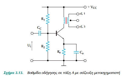
Figure 3.13. Step into a class A driver with transformer coupling
The Sch.3.14 shows two driving circuits using half way coupling, ie, direct coupling. Both circuits generate the same two output signals which have 180 ° phase difference of the input signal (reversal phase). The circuit presents Sch.3.14a small output impedance, while that of Sch.3.14 b shows large output impedance.
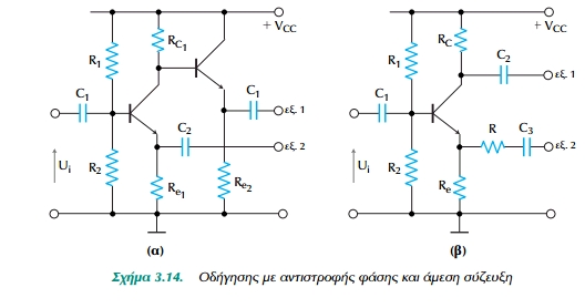
Figure 3.14. Driving in reverse phase and direct coupled
3.9 Amplifiers additional symmetry
An amplifier can operate as push-pull amplifier without transformers if we use two complementary symmetry transistors. Additional symmetry occurs when the pair of transistors of the push-pull transistor is a type npn, while the other is type pnp. The advantage of the additional symmetry is, what the transistor need only one input signal, unlike the typical circuits, in which two input signals must have a phase difference of 180 °.
The circuit shows the beginning Sch.3.15 action additional symmetry, which feeds the input signal while the input transistors. The positive half of the input signal makes conductive the transistor npn and positive half-wave input signal appears stronger in load RL. Between input and output there is no phase difference.
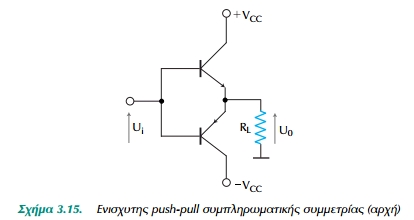
Figure 3.15. Amplifier push-pull complementary symmetry (top)
Now when the input signal is negative, then it becomes conductive and the transistor pnp output appears in the negative half-wave amplified input voltage. Note that when the input signal there is no circulating current through the transistor amplifier and therefore we have push-pull class B.
The Sch.3.16 shows a practical circuit amplifier push-pull complementary symmetry in class AB. The resistors R1 must be small to avoid relegation the input signal. The load RL (speaker) can be connected either directly (direct coupling) or adapted to output transformer. The resistors R, can be replaced by diodes, polarized at right time, to get better voltage stabilization.
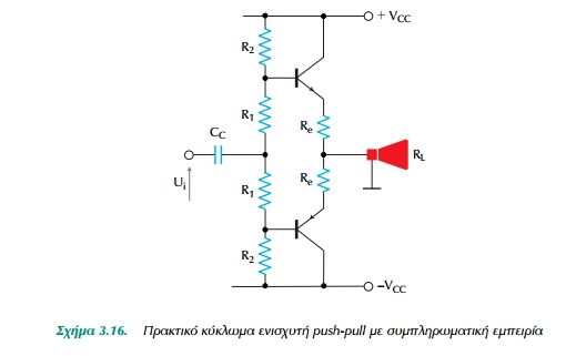
Figure 3.16. Practical circuit of push-pull amplifier with complementary experience
3.10 Amps applied on chip
Commercially available variety of integrated circuits (IC) that act as power amplifiers. In this section we present, as an example, the audio frequency power amplifier LM380 of National Sem. Co. and give a brief description of the hybrid amplifier with maximum output power 100 W. esodou
The LM380 is an audio frequency power amplifier that gives output power 2.5W (rms) to a load RL = 8 ohms The IC we need a minimum number of external components to operate.
The main performance is:
• Internal stable voltage gain 50 (34 dB).
• Output automatically driven at half the supply voltage.
• Protection of output short circuit with internal thermal limiting.
• Step input allows inputs to be grounded or put into ac coupling.
• crossing frequency bandwidth 100 kHz.
• Low distortion (about 0.2%).
The terminals Sch.3.17 shows the block diagram and schematic diagram of the LM380.
3.10.1 Description of the LM380 Circuit
As shown in the schematic circuit diagram of LM380 consists of four
tiers: a following emitter pnp, a differential amplifier and a complementary emitter following.
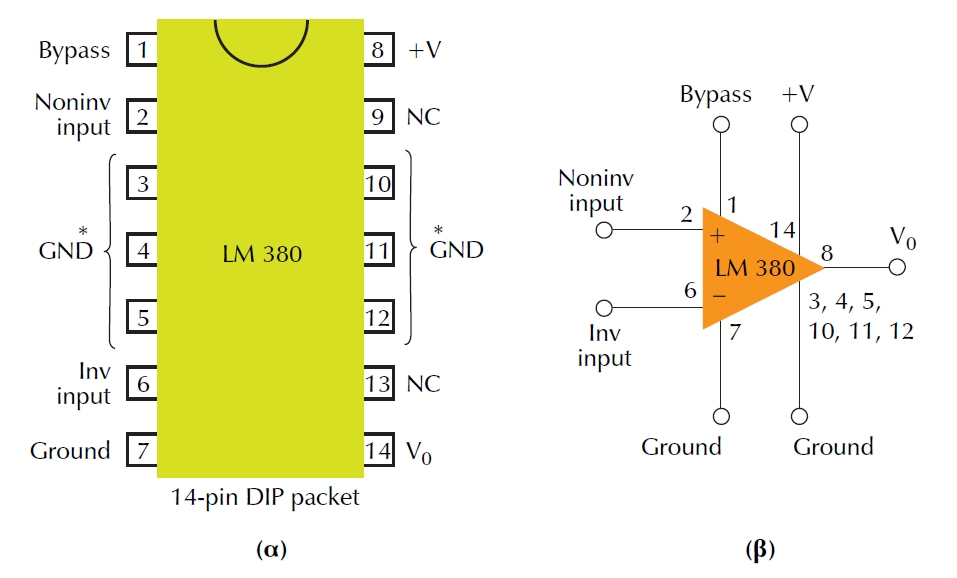
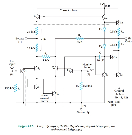
Figure 3.17. Power amplifier LM380. (Terminals, block diagram and circuit diagram)
The input stage is an emitter following which consists of transistors Q1 and Q2, and drives the differential pair pnp Q3-Q4. Proper selection of input transistor pnp Q1 and Q2 allows the entrance to refer to land so the input signal can directly be conjugate either to the inverting input (pin 6) or to the non-inverting input (pin 2) of the amplifier .
The normal flow in the differential pair pnp Q3-Q4 is created by combining Q7, R3 and + VCC. The mirror current that is generated by the transistors Q7, Q8 and produces the corresponding collector current of Q9. The transistors Q5 and Q6 collector currents create different pairs of pnp. The output of the differential amplifier are considering taking the union of the transistors Q4 and Q6 and amplified as input voltage gradient of the strengthening of the common emitter below.
This stage booster consists of common emitter transistors Q8, diodes D1 and D2 and Q9 as a source of load current. The capacitor C, between the base and collector of Q9, creates an internal hedge and helps maintain the upper cutoff frequency to 100 kHz with an output of 2 W 8 Ohm load Because Q7 and Q8 form a mirror current, the current through of D1 and D2 are approximately the same as the current in R1. In addition, D1 and D2 operate as temperature compensation diodes for transistors Q10 and Q11 because D1 and D2 have the same characteristics as the base-emitter diode of Q11. Therefore, the current through Q10 and the combination of Q11-Q12 is approximately equal to the current through the diodes D1 and D2.
The output stage of the complements of the following emissions is the transistor npn Q10 and Q12. In fact, the combination of transistor pnp Q11 and the transistor npn Q12 is capable of providing a power npn transistor and the performance characteristics of a transistor pnp.
Given the proper settlement of the output stage, the trend in a calm ¬ output is half the supply voltage (+ VCC). Moreover, the negative dc anasyzefxi applied through R5 balances the intermediate differential amplifier so that the dc voltage at the output to stabilize the price + VCC / 2. Uncoupled to the input circuit from the supply voltage + VCC, is a decoupling capacitor in the range of MF decoupling between the terminal (terminal 1) and earth (pin 7). The total internal reinforcement (gain) voltage of the amplifier is in principle stable in value 50, but applications can be increased using anasyzefxi positive, as we shall see below.
3-10.2 Applications of the LM380
The Sch.3.18 shows a simple audio frequency power amplifier as the most basic application of LM380. As shown in the figure, the amplifier needs few external components due to internal polarization, and fixed compensation payment. When the amplifier is used without a reversal, the inverting terminal can be grounded, or connected to earth through a resistor or a capacitor or be left open, as shown in the figure. Similarly, when the amplifier is used without a reversal, the non - inverting terminal can be shorted to earth or grounded through a resistor or a capacitor.
Usually, if the input source has a high internal resistance connect a capacitor between the inverted terminal and earth. In any connection the voltage + VCC must aposyzefchthei connecting a capacitor between terminal + VCC (pin 14) and the earth. Also used with a combination RC terminal output (pin 8) to ensure any missing oscillations 5 to 10 MHz, particularly in sensitive RF components.
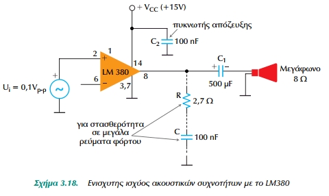
Figure 3.18. Audio frequency power amplifier with LM380
Although the strengthening of the LM380 is internally consistent (50 or 34 dB), can be changed using external elements. We can achieve up to 300 support using positive anasyzefxi. Eg the Sch.3.19 a shows the LM380 by using positive reinforcement 200 anasyzefxi. The Sch.3.19 b
shows LM380 variable shows up to support 50 by the simple technique of using potentiometer between pins entry.
Figure 3.19. Amplifier with LM380 anasyzefxi positive control for amplification of
The Sch.3.20 shows an application that needs more power than one that only gives an LM380. Here, two LM380 used as connection bridge to give more power. With this connection, the output voltage is twice that of an LM380 amplifier and therefore the power is transferred to the load is four times. In order to have better behavior of the circuit, potentiometer is used to balance the offset voltages at the output of the LM380.
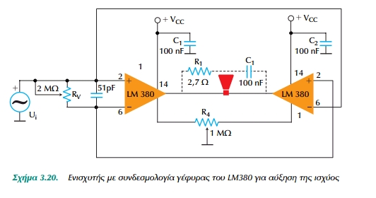 Figure 3.20. Amplifier with LM380 connection bridge for increased power
3.10.3 Other Integrated Power - Hybrid Power Amplifiers
Besides there are other LM380 integrated circuit IC power amplifiers like LM377 (dual), the LM378 (dual) and several others with various inputs of output. The dual power amplifier LM377, which gives 2 W / channel, is used as a stereo amplifier for tape recorders and recording instruments and amplifiers for stereo AM-FM.
For applications that require more power out of it we can get from the IC, uses hybrid power amplifiers, ie amplifiers combine discrete and integrated circuits. Such are, for example The Intersil
ICH8510/8520/8530, designed to give 1, 2 and 2.8 A, respectively, output voltage 24 V. All amplifiers have been protected with internal return and reduce power Short circuit protection on earth. Each amplifier has a dc strengthening 105 (100 dB), internal frequency compensation and electrically isolated enclosure allows easy heat dissipation. These provisions are also used to drive electron tubes, push-pull solenoids and motors dc and ac.
Another classic example of a hybrid power amplifier is that of Burr-Brown, the 3573, which gives peak 100 W or 40 W continuous output power. When supplied with mains voltage ± 28 V, ± 5 A gives minimum peak current at ± 20 V (40 V pp) to the load. The circuit
This has internal frequency compensation deformation good characteristics and low cost.
EXERCISES
- 3-1. A power amplifier using transformer transformation ratio of 10 and 4 Ohm Speaker Find the reflected impedance on the primary of the transformer.
- 3-2. A power amplifier output impedance is 2 KOhm and 8 Ohm speaker uses Lying transformation ratio of the transformer for optimum adjustment.
- 3-3. A power amplifier has 4.8 KOhm glancing resistance and transformation ratio 20. Find the resistance of the speaker.
- 3-4. To choose a suitable power amplifier transistor inverter, powered by +15 V supply voltage and load stimulates 4Ohm to a maximum return.
- 3-5.A push-pull amplifier class B, with a power adapter ac 2 W, RL = 4 Ohm and VCC = 15V. To select an appropriate transistor.
Comments
Review my weblog ... allen-bradley: http://automationafair.com
RSS feed for comments to this post