
Dual full recovery
3.7.2 Dual <Full Lift
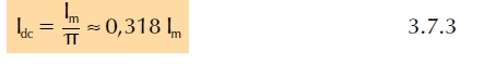
In the case of imianorthomenis voltage constant component
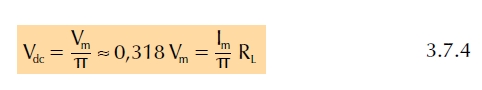
current and voltage esodou, as shown by the relations (3.7.3) and (3.7.4) is only 1 / π ie 31.8% of the maximum current and input voltage respectively. The small percentage that is because the diode circuit conducts only during the positive half period and therefore there is current and voltage at the load only during this half.
3.7.2.1 Double rectification with two (2) diodes
A solution to increase this percentage will be adding a second diode in circuit which gives power to the load during the negative half of the input voltage. Such a circuit shown in Figure (3.7.5). The circuit gives the so-called double <full recovery.
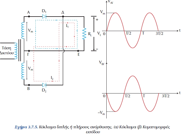
Figure 3.7.5. Dual circuit or full recovery. (A) Circuit (b) Input Waveforms
The mains voltage (220V, 50 Hz) is transformed into lower voltage in the secondary coil of the transformer, which has medium receive and provide two equal voltages with a maximum value Vm at two loops the circuit.
The median download the secondary coil of the transformer (point C) is connected to one end of the load resistor RL and the other end of resistor connected to the cathodes of diodes D1 and D2 (point D). The diodes are ideal.
During the half 0 <t <T / 2, point A is positive from the point C (VΑΓ = + Vm), while point B is Negative from the point C (VΒΓ =-Vm). This is because the secondary windings of the transformer coil is wrapped in the opposite direction. The diode D1 conducts and the circuit current is ADEGA and therefore the load RL, which is the current average price of imianorthosis I1dc = Im / 2. The diode D does not conduct, because it is reverse biased.
During the half -T / 2 < t <T is: V ΑΓ =-Vm, VΒΓ = + Vm.
Therefore the diode D2 conducts and the diode D1 does not conduct, because it is in reverse polarity. Thus, the circuit ΒΔΕΓΒ current passes I2 with mean Ι2dc = Im / 2. Therefore a voltage and current in Figure 3.7.6.
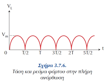
burden, as shown in Figure 3.7.6.
The voltage and load current at full lift
T / 2 T 3T / 2 2T 5T / 2
The mean rectified voltage and rectified current is given by relations (3.7.6) and (3.7.7) respectively.
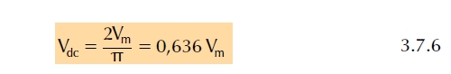
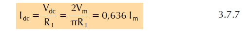
So, the average (dc) voltage and current at full lift is twice that in imianorthosi.
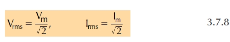
The corresponding effective (rms) value of the voltage and current at full lift is:
3.7.2.2 Dual diode bridge with a lift

Figure 3.7.7. Full recovery by a bridge diode
For complete recovery, is now used frequently layout of the bridge diodes. The diode bridge consists of 4 diodes connected as in Figure 3.7.7. With the bridge circuit avoids the use of transformer-making tools that are undesirable because of cost transformer.
During the positive half of the input voltage, the diodes D2 and D3 agoun (red arrows), while the diodes D1 and D4 are off. During the negative half-voltage diodes D1 and D4 agoun (blue dashed arrows), while diodes D2 and D4 are off. So the load L passing stream of everything that you wear and price equal to the average value given by equation (3.7.7).
In full bridge rectification with the average value of both the voltage and current are the same as in full recovery with 2 channels, and the rms voltage (relations 3.7.6, 3.7.7, 3.7.8) . H bridge tolls will be analyzed in B 'class.
3.7.3 Peak Detector (Super Capacitor)
As mentioned in previous paragraphs 3.7.1 and 3.7.2,
The lift is an electronic process for smoothing the AC voltage and DC output. The output voltage is constant while but not stable and varies with different amount of variation in imianorthosi and full recovery. The fluctuating trend can not be used to power electronic devices because it creates problems of noise, hum or distortion in amplifiers, transmitters, receivers, etc.
The variance of the voltage can be lowered by placing suitable filters. The filters are electronic devices a smooth trend, cut out unwanted frequencies allow signals to pass useful frequencies. The simplest and most important filter is the filter capacitor. A capacitor that is placed at the output of the circuit imianorthosis or full recovery in parallel with the load resistor as in Figure 3.7.8.
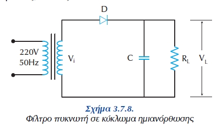
Figure 3.7.8.
Filter capacitor in circuit imianorthosis
During the positive half of the input voltage, the capacitor gets charged and the maximum rate, Vm, on top of the input voltage.
When the voltage decreases the capacitor begins to be discharged on the load resistor RL. The discharge of the capacitor continues during the negative half-and stops only at the next positive half period.
Figure 3.7.9 The discharge is represented by line segments, which start from the top of imianorthomenis voltage and reach up to a point in the next half-wave.
The slope of these straight sections depends on the time constant (t = CR) of the capacitor and resistor. For a given value of the capacity C, we distinguish the following cases:
a. load resistance is too large, theoretically infinite (R = ∞). then the capacitor is not discharged and the output voltage remains constant in value, and VL = Vm (case I).
b. The time constant of resistor and capacitor, t = CR, is much longer than the period of the sinusoidal input voltage (t >> T). Then the capacitor will discharge very slowly and the slope of the straight discharge is very small (case II).
c The time constant is very large and is comparable with the period of tension (T> T). Then the capacitor ekforizetai quickly and the voltage value of nearly zero again loaded before the next positive half-voltage (case III).
It is obvious that to get good recovery should prefer the case I (NK = 0) or even the II (NK> 0), so the output voltage (voltage across the capacitor) is closer to the peak voltage of imianorthomenis.
Ripple voltage, Vk, are the boundaries within which range the output voltage <the voltage of the capacitor.

Figure 3.7.9. Trends imianorthoti filter capacitor
it turns out that:
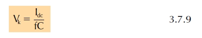
where: Idc = the average output current
f = frequency of input voltage
C = the capacitance of the capacitor.
Therefore, the constant output voltage is:
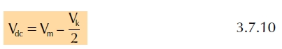
O imianorthotis the filter capacitor discussed above is also called peak detector because the output voltage has a value equal to the peak voltage of the rectifier.
In the case of full recovery, the ripple is less because there is output voltage and the positive and negative half-, when the capacitor has at his disposal much less time to discharged until the next charge. In this case:
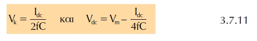

Figure 3.7.10
Full output voltage rectifier with filter capacitor
There are other filters such as smoothing the voltage filter inductor, filter type P with capacitor and resistor, capacitor and inductor, L type filter etc. but they will not deal here.